
(How-To) Configure NSX-T Uplink Profiles
An Uplink Profile defines how an N-VDS residing on a respective transport node will map to the physical NICs of a host. The configurable properties of an uplink profile determines how transport nodes connect to the physical network by configuring the number of NICs, teaming policies, VLANs and MTU.
The benefit of creating a custom uplink policy allows you to configure the desired state once and enforce that desired state everywhere. Thus, creating a consistent and reliable deployment.
1) Login to the NSX manager web UI
2) Navigate to System > Fabric > Profiles > Uplink Profiles

3) Click + ADD and fill in the details
- Name: Name of the uplink profile. Try to make the name meaningful and include if the profile should be used for transport nodes (hosts) or edges since you can have multiple uplink profiles and apply them to different objects
- Description: optional

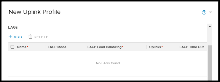
You can create a LAG to be used with the uplink profile by clicking the +ADD link in the LAGs section.
Specify the fields below
Name: Name the LAG
LACP Mode: Active or Passive
- Active: This LAG initiates the sending of LACP-PDU messages to its upstream partner
- Passive: This LAG will only respond to received LACP-PDU messages from its upstream partner
Note: for an LACP group to establish at least one partner MUST be in an ‘Active’ state sending out LACP-PDU messages
| Peer 1 | Peer 2 | Comments |
| Active | Active | The links will aggregate once the LACP negotiation is successful |
| Active | Passive | The links will aggregate once the LACP negotiation is successful |
| Passive | Passive | LACP will not be successful |
LACP Load Balancing: Select the load balancing policy from the list
Available LAG teaming policy options:
- Source MAC address
- Destination MAC address
- Source and destination MAC address
- Source and destination IP address and VLAN
- Source and destination MAC address, IP address, and TCP/UDP port
Uplinks: Enter the number of uplinks that will be apart of this LAG
LACP Time Out: Fast or Slow
- Fast: An LACP-PDU message is sent out every 1 second
- Slow: An LACP-PDU message is sent out every 30 seconds
Note: The use of multiple LAGs is not supported with KVM hosts
Down at the bottom you can customize a teaming policy, determine the number of active uplinks, and standby links. The names you use for the uplinks on this page will propagate to other objects associated with this profile.
Available teaming policy options:
- Failover Order: An active uplink is specified along with an optional list of standby uplinks. If the active uplink fails, the next uplink in the standby list replaces the active uplink. No load balancing is performed with this option.
- Load Balance Source: A list of active uplinks is specified, and each interface on the transport node is pinned to one active uplink. This configuration allows use of several active uplinks at the same time.
- Defined standby links with this teaming policy is not supported.
- Load Balance Source MAC: A list of active uplinks is specified, and the uplink used is determined based on the source VM’s MAC address.
- Defined standby links with this teaming policy is not supported.
Note: KVM hosts only support the ‘Failover Order’ teaming policy
I would recommend you name the uplink NICs something meaningful so you can identify them from the transport nodes perspective as these names will be reference later when you create your transport nodes. This will be especially useful if you need to perform any data path maintenance or troubleshooting.
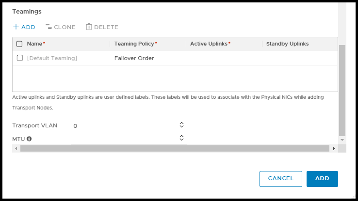
Next, we will need to configure the Transport VLAN and MTU of the links.
The Transport VLAN is the VLAN all communication with which this Uplink Profile is attached will be tagged
Note: If you leave the MTU field blank it will default to 1600 MTU
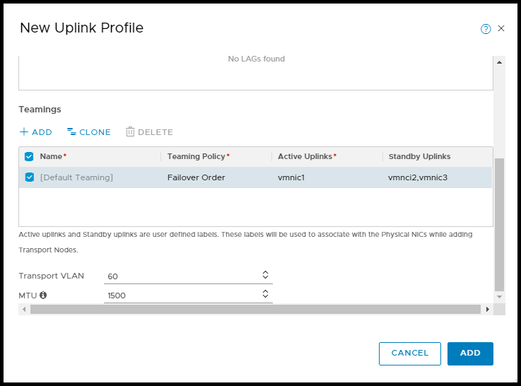
When complete, click ADD

You can repeat the process again and create many uplink profiles crafted specifically to your deployment needs for both overlay and VLAN backed networks as well as tailored uplink profiles for both transport nodes and edge nodes.
